Sections

Journey — Internal Presentation

Gaussian Splat
Generation Pipelines

From cameras to splats — CG, Real-Time, and Real-World

Adelina  /  Journey  /  March 2026

iteration: 0 loss: 1.000 gaussians: 500
01 / 19
Background

What Are Gaussian Splats?

A scene is represented as millions of 3D Gaussians — oriented ellipsoids floating in space. Each one carries enough information to describe a tiny patch of a surface or volume.

rendering diagram...

Per-Gaussian Properties

  • Position — XYZ center in world space
  • Covariance — rotation quaternion + 3D scale (the ellipsoid shape)
  • Opacity — alpha value, learned per-Gaussian
  • Spherical Harmonics — view-dependent color (captures specularity)

Key Insight — Explicit Representation

3DGS is an explicit representation — geometry and appearance are stored directly as discrete Gaussians in 3D space. This enables real-time rasterization: Gaussians are sorted by depth and alpha-composited onto the screen, achieving 30–120 fps on modern hardware.

Kerbl et al., 3D Gaussian Splatting for Real-Time Radiance Field Rendering, SIGGRAPH 2023

Training Process

Training starts from the sparse SfM point cloud and runs for 7,000–30,000 iterations. Each iteration renders the current Gaussians from a training camera view, computes a loss against the ground-truth image, and backpropagates. The loss is a combination of L1 pixel error (absolute brightness difference) and D-SSIM (structural similarity, which penalises blurry or structurally wrong regions). L1 catches overall brightness; D-SSIM catches texture and edge fidelity.

Adaptive density control runs periodically during training: Gaussians in under-reconstructed regions are cloned (a small Gaussian is duplicated to fill a gap) or split (an over-large Gaussian covering a fine-detail region is replaced by two smaller ones). Gaussians with near-zero opacity are pruned — they contribute nothing and just waste memory. This is how the model grows from ~100k initial points to millions of Gaussians.

Point cloud quality directly affects convergence. A dense, accurate SfM cloud gives training a solid starting geometry — the Gaussians only need to refine, not discover structure. A sparse or noisy cloud means the model must compensate for bad initialisation, requiring more iterations and often converging to a worse result or not at all.

Training Visualization

Gaussians refining from noise → coherent scene representation

02 / 19
Overview

How It's Made — The Pipeline

Images Any source
SfM COLMAP
Sparse Cloud + Camera Poses
Training PostShot
.ply
Raw Splat .ply file
Clean splat-transform
Web .sog → PlayCanvas
Input

Images

Raw input from any source — renders, photos, video frames. Coverage from many angles with 60–80%+ overlap between adjacent views.

Step 1

Structure from Motion (SfM)

Detects features, matches across images, triangulates a sparse 3D point cloud, and estimates camera poses. For CG pipelines with known poses, we skip pose estimation and run only point_triangulator.

COLMAP 3.x — open-source, incremental SfM. Registers one image at a time. Battle-tested.
Reality Capture — commercial, global SfM. Registers all images simultaneously. Faster on large datasets.
Step 2

PostShot Training

Takes COLMAP output (sparse cloud + camera poses), trains Gaussian splats over thousands of iterations. Exports .ply — the raw splat file (100 MB – 2 GB).

Step 3

Clean (splat-transform)

Remove ghost splats (near-zero opacity), spatial outliers, and unused SH bands. Strip floaters before compression.

Step 4

SOGS Compression

10–20× compression for web delivery. Morton code sorting → spatial chunking → quantization → progressive streaming. A 500 MB .ply becomes a 25–50 MB .sog.

Web delivery — PlayCanvas / SuperSplat viewer, real-time in browser

03 / 19
Fundamental Principle

The splat is only as good as the images you feed it

The quality of a Gaussian splat is fundamentally bounded by the quality and coverage of the input images. Garbage in, garbage out.

Coverage

Every surface that needs to exist in the splat must be visible from multiple angles. Occluded regions become missing geometry.

Overlap

Adjacent frames must share enough features for matching to work. 60–80% overlap is the target. Too sparse and SfM fails silently.

Quality

Blur, motion smear, inconsistent exposure, and texture-less surfaces all reduce reconstruction quality. The splat can't invent detail that isn't there.

Texture Is Everything

Flat white walls, glass, mirrors, and water are the enemies of photogrammetry. SIFT needs distinctive visual features to establish correspondences — if a surface has no texture, COLMAP literally cannot see it. Featureless regions produce no matches, no triangulation, and become holes or floaters in the splat. This is true for both CG renders and real-world captures.

Consistent Lighting

Consistent lighting across all frames is non-negotiable. Mixed sun/shadow (clouds passing overhead mid-capture) or HDR auto-exposure changes make the same surface look different in different frames. This confuses both feature matching (the descriptor changes) and training (the model can't agree on the true colour of a point). For real-world captures, shoot during a single overcast session or in stable golden-hour light — not mid-day with shifting clouds.

Moving Objects = Floaters

Trees swaying in the wind, people walking through frame, and cars moving through a scene all create "floaters" — phantom Gaussians that appear to hover in empty space. The SfM and training process interprets these moving objects as inconsistent 3D structure, and compensates by placing semi-transparent Gaussians at multiple positions. For CG pipelines this is not a concern. For real-world captures, choose your timing carefully: early morning for minimal pedestrian/vehicle traffic.

04 / 19
Key Insight

More Images ≠ Better Quality

This is a common trap. After sufficient coverage, additional frames add render time and training time but not quality. What matters is coverage and angular diversity, not sheer volume.

QUALITY vs FRAME COUNT

Frame Count Quality 50 100 200 400 600+ sweet spot ~120-200 frames diminishing returns wasted render time

What Actually Matters

  • Coverage — every surface visible from 2+ angles
  • Angular diversity — cameras spread around the subject
  • Overlap — adjacent frames share 60–80% of view
  • Consistent lighting — no exposure jumps between frames

The Real Trade-off

A well-planned 150-frame capture can outperform a careless 500-frame capture. The balance: enough frames for overlap + angular diversity, but not so many that you waste hours of render or flight time.

Frame step matters too: rendering every frame vs every 2nd or 5th frame of an animation controls density without changing the camera path.

Diminishing returns curve: quality improves steeply from 50–150 frames as coverage fills in, plateaus around 200–300 frames once all surfaces are well-covered from multiple angles, and additional frames beyond that are essentially pure overhead — they add render time, matching time, and training time without meaningfully improving the splat.

COLMAP matching is O(n²): exhaustive matching compares every image against every other image. For 200 images that is 19,900 pairs. For 400 images it is 79,800 pairs — four times the work for twice the images. Doubling your frame count quadruples COLMAP matching time. For 500 images you are comparing 124,750 pairs. This is why large drone captures can take hours in COLMAP before training even starts. Render time, COLMAP matching, and PostShot training all scale with frame count — the cost compounds.

05 / 19
Technical Deep-Dive

Structure from Motion — Step by Step

SfM recovers both the 3D structure of a scene and the camera poses simultaneously, using only overlapping images as input.

Feature Detection (SIFT)Find keypoints in each image — corners, edges, blobs
128-dim descriptor per keypoint
Feature MatchingCompare descriptors across all image pairs
Nearest-neighbor + Lowe's ratio test + RANSAC filtering
TriangulationTwo+ views of same point →
calculate 3D position via ray intersection
Bundle AdjustmentJointly optimise ALL camera poses + ALL 3D points
Minimise total reprojection error
OutputSparse Point Cloud + Camera Poses

Feature Detection — Visualized

SIFT scans the image at multiple scales, finding visually distinctive keypoints — corners, edges, blobs — that can be reliably re-identified from different angles.

Keypoints detected at corners and edges — circle radius = detection scale

Feature Matching — Visualized

SIFT detects keypoints in each image. Descriptors are compared to find the same physical point across views.

Photogrammetric Triangulation
Frame 001 Frame 002 Frame 003 V1 V2 V3 V4 V5 FRAME 001 FRAME 002 FRAME 003 IDENTICAL FEATURE POINTS CAMERA MOVEMENT
1
Feature Detection (SIFT)

Scale-Invariant Feature Transform. Finds keypoints at corners, edges, blobs — robust to scale and rotation changes. Each keypoint gets a 128-dim descriptor.

2
Feature Matching

Compare descriptors across image pairs. Nearest-neighbor matching with Lowe's ratio test. RANSAC filters outlier matches geometrically. Result: thousands of verified correspondences.

3
Triangulation

Two+ rays from different camera positions to the same image point. Intersect the rays in 3D space → recover the point's world position. Requires at least two views.

4
Bundle Adjustment

Global non-linear optimization. Jointly refine all camera poses and all 3D point positions to minimize reprojection error across all images simultaneously.

5
Output

Sparse 3D point cloud + calibrated camera poses. This is the input to PostShot. For CG pipelines we skip most of this — known poses mean only triangulation is needed.

06 / 19
Technical Deep-Dive

COLMAP 3.x Pipeline — Detailed

All commands and workflows here are COLMAP 3.x. COLMAP 4 is in active development with improved feature matching, better GPU acceleration, and a modernised architecture — worth watching, but our current pipelines rely on COLMAP 3.x which is battle-tested and widely supported.

ExtractSIFT keypoints
per image
Match + VerifyExhaustive or sequential
+ RANSAC filtering
TriangulateKnown poses → fast
Full SfM → estimate
Bundle Adj.Global
optimisation
OutputSparse cloud
+ poses
1
Feature Extraction

SIFT keypoint detection and descriptor extraction from every image. The keypoints are what COLMAP matches across images.

2
Feature Matching + Verification

Exhaustive matching for dome captures (every image vs every other). Sequential matching for video. COLMAP internally runs RANSAC to filter outlier matches geometrically. Exhaustive matching is O(n²) — for 200 images that is 19,900 pairs; for 500 images it is 124,750 pairs. This is why matching can take several hours for large real-world captures. For drone datasets with thousands of images, consider sequential or vocabulary-tree matching to keep matching tractable.

3
Triangulation or Full SfM

CG pipeline: known poses → point_triangulator only. Fast, because pose estimation is skipped — COLMAP simply projects rays from the known camera positions and finds where they intersect. Real-world pipeline: incremental SfM — COLMAP estimates poses from scratch, one image at a time, growing from a seed pair. Slower and more sensitive to bad input, but handles the uncertainty inherent in real captures.

4
Bundle Adjustment

The most computationally expensive step — and also where the most quality is gained. Bundle adjustment jointly optimises ALL camera poses and ALL 3D point positions simultaneously, minimising total reprojection error across every image at once. This is a large sparse non-linear least-squares problem. For 500 images it can involve millions of variables. Only needed in full SfM mode; when poses are already known (CG pipeline), it is skipped entirely.

COLMAP 3.x — manual PowerShell commands (use when the .bat fails):

# 1. Feature extraction — note camera model params
colmap feature_extractor `
  --database_path .\database.db `
  --image_path .\images `
  --ImageReader.camera_model PINHOLE `
  --ImageReader.single_camera 1 `
  --ImageReader.camera_params "3200.5,3200.5,1920,1080"
# 2. Exhaustive matching (for dome captures)
colmap exhaustive_matcher `
  --database_path .\database.db
# 3. Triangulation from known poses
colmap point_triangulator `
  --database_path .\database.db `
  --image_path .\images `
  --input_path .\sparse\0 `
  --output_path .\triangulated
# 4. Inspect result (optional)
colmap gui `
  --database_path .\database.db `
  --image_path .\images `
  --import_path .\triangulated
COLMAP dome camera visualization

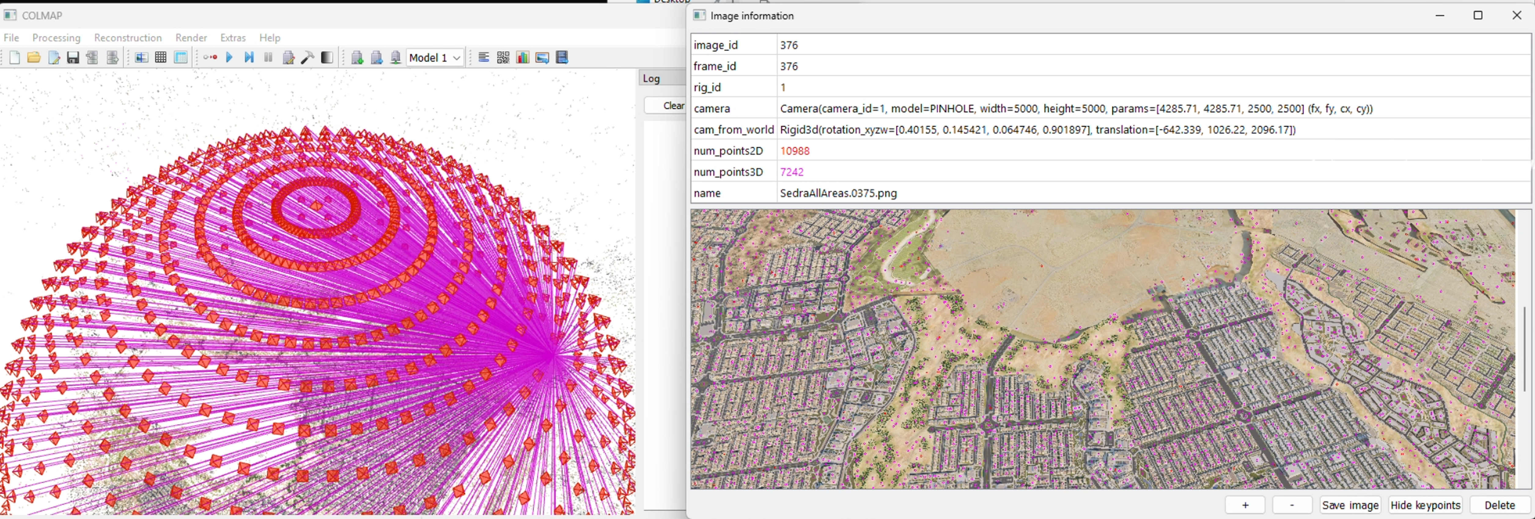
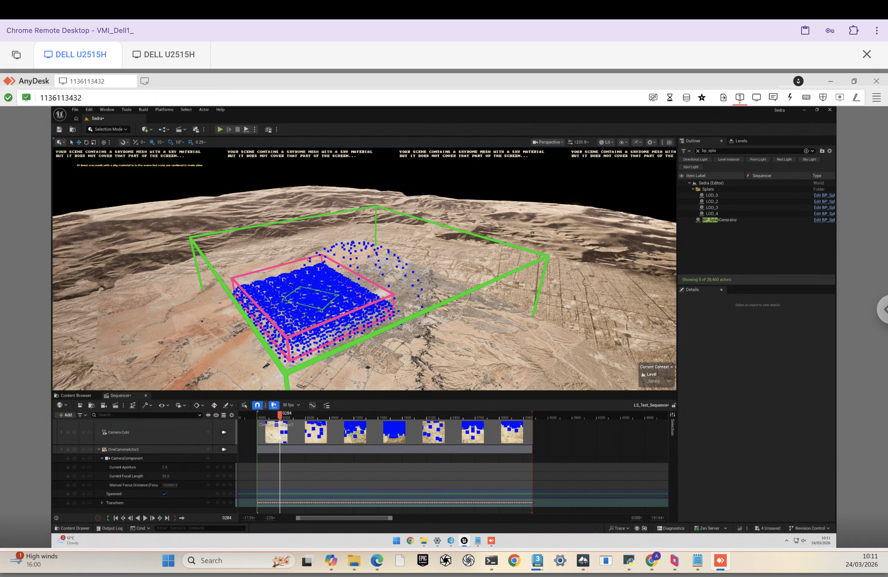
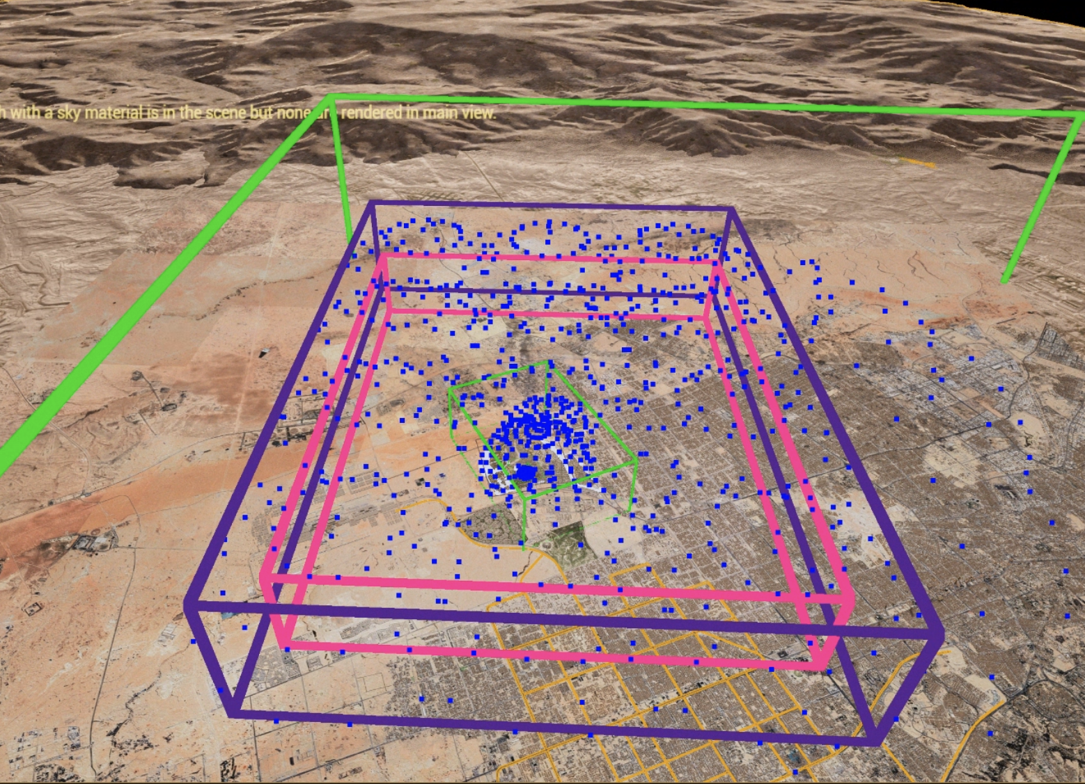
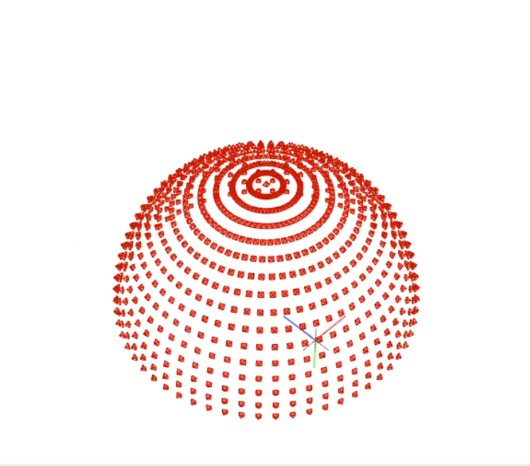
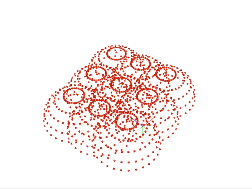
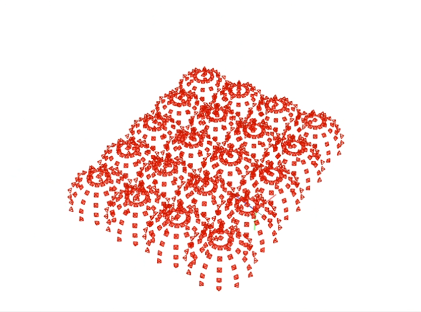
COLMAP — dome camera distribution with projection rays + aerial render

COLMAP 4 — What's New

COLMAP 4 is a significant upgrade over 3.x. Our pipelines currently use 3.x, but 4 is worth migrating to:

ALIKED neural features

Replaces SIFT with a learned feature detector. More robust on textureless surfaces, repetitive patterns, and challenging lighting. Fewer failed registrations.

GLOMAP global mapper

Global SfM instead of incremental. Registers all images simultaneously rather than one at a time. Significantly faster on large datasets and more robust to weak connectivity.

Better GPU acceleration

Feature extraction and matching run faster on GPU. Matching 500+ image datasets that took hours in 3.x can finish in minutes.

LightGlue matching

Neural matcher that replaces brute-force nearest-neighbor. Handles viewpoint changes and lighting variation much better than traditional descriptor matching.

Migration path: our batch GUI already detects COLMAP version and unlocks v4 features automatically. The COLMAP format (cameras.txt, images.txt) is unchanged — downstream pipeline stays the same.

07 / 19
Technical Deep-Dive

Camera Models — Compared

Every camera — virtual or real — is described by a mathematical model. Choosing the wrong one in COLMAP is a silent failure: it runs, it produces output, but the reconstruction quality suffers.

ModelParamsDistortionUse CasePipeline
SIMPLE_PINHOLE3 — f, cx, cyNoneSquare-pixel virtual cameras, quick testsCG (simple)
PINHOLE4 — fx, fy, cx, cyNoneVirtual cameras with non-square pixels or known separate focal lengthsCG (Max, UE)
SIMPLE_RADIAL4 — f, cx, cy, k11 radialReal cameras with mild barrel/pincushionDrone (simple lens)
RADIAL5 — f, cx, cy, k1, k22 radialReal cameras with moderate distortionDrone
OPENCV8 — fx, fy, cx, cy, k1, k2, p1, p22 radial + 2 tangentialComplex distortion — safe default for real lensesDrone (recommended)
OPENCV_FISHEYE8 — fx, fy, cx, cy, k1–k44 fisheyeUltra-wide / fisheye lenses (>120° FOV)Drone (wide-angle)
FULL_OPENCV12 — fx, fy, cx, cy, k1–k66 radialSevere or unusual distortion profilesRare / calibrated rigs

CG = Perfect Pinholes

Virtual cameras have zero distortion — no barrel, no pincushion, no rolling shutter, no chromatic aberration. COLMAP triangulation is exact. Use PINHOLE or SIMPLE_PINHOLE. Adding distortion params to a perfect camera wastes degrees of freedom and can make reconstruction worse.

Real Cameras = Always Distorted

Every physical lens introduces distortion. OPENCV is the safe default for drone captures — models both radial (barrel/pincushion) and tangential (decentring). Using PINHOLE on real images means COLMAP can't model lens bending → worse matches → worse splat. No error — just a worse result.

Shared Foundation — Pinhole Projection

All models share the same base projection. Distortion models add correction terms before the projection maps 3D → 2D.

# Base projection (all models)
u = fx * (X / Z) + cx    v = fy * (Y / Z) + cy

# Radial + tangential distortion (OPENCV)
r² = x² + y²
x' = x·(1 + k1·r² + k2·r⁴) + 2·p1·x·y + p2·(r² + 2·x²)
y' = y·(1 + k1·r² + k2·r⁴) + p1·(r² + 2·y²) + 2·p2·x·y

The Rule

CG renders → PINHOLE. Real cameras → OPENCV (or OPENCV_FISHEYE for ultra-wide). Never use PINHOLE on real images. Never add distortion params to virtual cameras. Getting this wrong won't crash — it just silently degrades your splat.

08 / 19
Critical Knowledge

Coordinate Systems

The Problem

Every tool in the pipeline uses a different coordinate system. Getting this wrong produces invisible failures — COLMAP runs, PostShot trains, but the result is wrong or unusable. No error messages. Just a bad splat.

The Three Systems

Software Handedness Up Axis Forward Units
3ds Max Right-handed Z-up +Y forward Centimetres
Unreal Engine Left-handed Z-up +X forward Centimetres
COLMAP / PostShot Right-handed Y-up -Z forward Metres

Max COLMAP Conversion

X_colmap =  X_max * 0.01
Y_colmap =  Z_max * 0.01    // Z-up → Y-up
Z_colmap = -Y_max * 0.01    // flip + scale

The Y axis becomes the new up axis. Max's forward (+Y) becomes COLMAP's -Z. All positions scaled by 0.01 (cm → m).

UE COLMAP Conversion

X_colmap =  X_ue * 0.01
Y_colmap =  Z_ue * 0.01     // Z-up → Y-up
Z_colmap = -Y_ue * 0.01     // flip handedness + scale

UE is left-handed with Z-up. The handedness flip and Z→Y swap combine into the same formula as Max, since both share Z-up / centimetre units.

Unit Conversion

Both Max and UE work in centimetres. COLMAP works in metres. Multiplying all positions by 0.01 handles this. Forgetting it gives you a scene that is 100× too large — COLMAP and PostShot will still run, but the splat will look like noise because the Gaussian scale and scene scale are wildly mismatched.

The reason coordinate bugs are so dangerous: most of them do not crash. They produce output that looks almost right but is subtly wrong. A sign flip on one axis makes the splat appear mirrored — you might not notice until the client asks why all the text is backwards. A missing cm→m conversion makes the scene 100× too large, which can still produce a splat, but every Gaussian is initialised at a scale calibrated for a metre-scale scene, not a 100-metre scene — the result is blurry, noisy, and never fully converges. A wrong axis mapping can produce a splat that looks fine from one angle and falls apart from another. There is no error log. The only indication is that the result looks wrong.

Why Quaternions?

Camera orientations in images.txt are stored as quaternions (QW, QX, QY, QZ), not Euler angles. Here is why.

Euler Angles — what you are used to

  • Rotation as three angles: pitch, yaw, roll
  • Suffer from gimbal lock — when two axes align (e.g. pitch = 90°), you lose one degree of freedom
  • Result depends on rotation order (XYZ ≠ ZYX ≠ YXZ)
  • Interpolation between orientations is jerky and non-uniform

Quaternions — what COLMAP uses

  • A 4D number: q = w + xi + yj + zk (stored as QW, QX, QY, QZ)
  • No gimbal lock — can represent any orientation smoothly
  • Order-independent
  • Smooth interpolation (SLERP) between orientations
  • Compact: 4 numbers vs a 3×3 rotation matrix (9 numbers)
  • Not human-readable — you cannot look at (0.9914, -0.1243, 0.0216, 0.0411) and know the angle

Both cubes perform the same rotation sequence: yaw 90° → pitch 90° → roll 180°. Watch what happens when pitch hits 90°.

Euler Angles

At pitch = 90°, yaw and roll axes collapse onto the same axis. The cube loses one degree of freedom — it can only spin one way. This is gimbal lock.

Quaternion (SLERP)

Same rotation, no lock. Quaternions interpolate on a 4D hypersphere — every orientation is reachable from every other, smoothly.

The Format in images.txt

# IMAGE_ID  QW     QX      QY      QZ      TX     TY     TZ    CAM_ID  NAME
1           0.9914 -0.1243 0.0216  0.0411  -2.34  1.82   5.62  1       frame_0001.jpg
# QW QX QY QZ = world-to-camera rotation quaternion
# TX TY TZ   = camera position (Y-up, metres — already converted)

Key Point for the MaxScript

The MaxScript reads Max's rotation matrix, converts the coordinate system (Z-up → Y-up), then converts to quaternion. This is where bugs are most likely to hide. If your splat looks twisted or inside-out, the quaternion conversion is the first thing to check.

09 / 19
Troubleshooting

When Things Go Wrong — Common Failures

Floaters

Semi-transparent blobs floating in empty space — the most common artifact.

Caused by: moving objects during capture, insufficient overlap between frames, textureless regions that confuse the optimiser.

Missing Geometry / Holes

Gaps in the reconstruction where surfaces should exist.

Caused by: insufficient coverage, occluded areas never photographed, glass and mirrors confusing SfM feature matching.

Coordinate System Bugs

Splat appears mirrored, rotated 90°, or 100× too large/small.

Caused by: axis swap errors, unit conversion mistakes (cm vs m), quaternion sign errors. These don't crash — they just produce a bad splat.

Blurry / Mushy Splats

Loss of fine detail — the splat looks soft and undefined.

Caused by: motion blur in source images, too few training iterations, camera too far from the subject.

Color Banding / Inconsistency

Patches of wrong color across the splat surface.

Caused by: auto white balance enabled during capture, mixed lighting conditions, auto exposure changing between frames.

Failed SfM Registration

COLMAP registers only a fraction of the input images.

Caused by: insufficient overlap between views, repetitive facades (buildings with identical windows), textureless surfaces that produce no feature matches.

If your capture is bad, start over. Don't try to fix it downstream.

Post-processing can remove floaters and clean up edges, but it cannot recover missing geometry or fix fundamentally bad camera poses. A clean recapture is almost always faster than trying to salvage a bad one.

10 / 19
Before We Dive In

Why Not Just Use PostShot?

PostShot has a built-in SfM engine. You can drop images straight in and get a splat. So why build pipelines at all?

When it works

If you have good images with decent overlap and you just need a quick result — PostShot's built-in SfM is fine. This is the fastest path for a proof-of-concept or quick test.

Good for: quick previews, testing if a capture is viable, small scenes with simple geometry.

When it doesn't

  • No camera pose control — if SfM fails, you can't provide known poses
  • No triangulation tuning — COLMAP gives you control over matching strategy, camera model, RANSAC thresholds
  • No batch processing — one scene at a time, manual each time
  • Black box debugging — when the splat looks wrong, you don't know if it's the SfM, the training, or the input
  • No CG pipeline at all — PostShot can't accept pre-computed camera poses from Max or UE without COLMAP format data

Why pipelines exist

Our pipelines give us control at every stage. We can provide known camera poses (skipping SfM entirely for CG), choose matching strategies, inspect intermediate results, batch-process dozens of projects, and debug failures by isolating which step went wrong. PostShot is the training engine — but everything upstream needs to be right for it to produce a good result.

11 / 19
Three Approaches

Our Pipelines

Same downstream process — different image acquisition strategies, each with distinct trade-offs.

1 — CG Pipeline

Tool: 3ds Max + MaxScript

Virtual cameras, full control over placement, coverage, and render settings. Highest fidelity via V-Ray path tracing.

+ Known camera poses — no SfM estimation needed
+ Perfect lighting control — repeatable, no weather
+ Highest material fidelity — V-Ray path tracing
5–20 min per frame — 150 frames = 12–50 hours
Requires 3D model + materials to exist
Domain gap — splat looks CG, not real

2 — Real-Time Pipeline

Tool: Unreal Engine + internal plugin

Plugin auto-generates camera dome, near-instant renders. Scene to splat in under 30 minutes.

+ Seconds per frame — 30 min full turnaround
+ Rapid iteration — test camera setups quickly
+ Auto COLMAP export — no manual conversion
Lumen GI is approximate — not path-traced
Requires UE scene to exist (asset pipeline)
Material quality below Max/V-Ray for hero assets

3 — Real-World Pipeline

Tool: Drone / photogrammetry camera

Physical capture. No 3D model needed — reality is the asset. Planning and conditions are the challenge.

+ Authentic materials — no domain gap at all
+ No 3D model required — capture what exists
+ Fine detail for free — weathering, vegetation, wear
Lighting baked in — no relighting, no golden hour
SfM can fail on glass, reflections, textureless walls
Weather, access, regulations — physical constraints

Shared downstream: All three feed into the same process — COLMAP triangulation → PostShot training → .ply export → SOGS compression → web delivery. The pipelines diverge only at image acquisition.

Pipeline Comparison

Aspect 3ds Max (CG) Unreal Engine Drone (Real-World)
Capture timeCamera setup: 1-2hPlugin setup: 15minFlight: 30-60min
Render time5-20 min/frameSeconds/frameN/A (real photos)
COLMAP timeMinutes (known poses)Minutes (known poses)Hours (full SfM)
Training time30min-2h30min-2h30min-2h
Total turnaround1-2 days30-60 minutes2-6 hours
QualityHighest fidelityGood (Lumen)Authentic materials
RepeatabilityFullFullWeather-dependent
12 / 19
Pipeline 1 — 3ds Max

CG Pipeline — 3ds Max

How It Works

  1. Set up camera animation path in 3ds Max (domes, spirals, circular orbits)
  2. Render animation frames — 5–20 min per frame, typically 150+ frames
  3. Export camera data via MaxScript → cameras.txt + images.txt
  4. MaxScript handles coordinate conversion: Z-up (Max) → Y-up (COLMAP), cm → m
  5. Run COLMAP 3.x for triangulation (known poses → triangulation only, not full SfM)
  6. Train in PostShot → .ply → SOGS compress

Camera Formations

Coverage strategy is everything. Three primary formations, used in combination:

Dome Formation

Hemisphere of cameras pointing inward. Primary tool for architectural details.

Spiral Orbit

Gradual upward spiral. Ensures vertical continuity across all heights.

Circular Orbits

Fixed elevation sweeps at low/mid/high. Good for horizontal surfaces.

Animated camera traversing dome positions in 3ds Max

What 3ds Max Exports

The MaxScript exports two things: the rendered frames (JPEG images from the animation), and a complete COLMAP-format dataset describing where each camera was when it took each frame. This means COLMAP doesn't need to figure out the camera positions — it already has them.

Rendered Frames

Each animation frame becomes a training image. 150+ JPEGs in images/

COLMAP Dataset

Camera intrinsics + per-frame position and rotation, written directly in COLMAP's text format

Camera Data Format

The COLMAP dataset consists of two text files. cameras.txt defines the lens — focal length and sensor center (same for every frame since it's one virtual camera). images.txt defines where that camera was for each frame — a quaternion for rotation and a translation vector for position.

cameras.txt — one camera, shared by all frames

# CAMERA_ID MODEL WIDTH HEIGHT PARAMS[]
1 PINHOLE 3840 2160 3200.5 3200.5 1920.0 1080.0
# fx      fy     cx      cy
# Focal length from FOV, principal point at image center

images.txt — one line per frame (position + rotation)

# IMAGE_ID QW QX QY QZ TX TY TZ CAMERA_ID NAME
1 0.9914 -0.1243 0.0216 0.0411 \
  -2.341 1.820 5.620 1 frame_0001.jpg
# Quaternion (world→cam rotation) + translation

Project Folder Structure

/project_root/ ├── colmap-postshot-workflow.bat ├── images/ │ ├── frame_0001.jpg │ ├── frame_0002.jpg │ └── ... (150+ frames) ├── sparse/0/ │ ├── cameras.txt # intrinsics from MaxScript │ ├── images.txt # extrinsics from MaxScript │ └── points3D.txt # empty — COLMAP populates └── triangulated/ # COLMAP output, fed to PostShot

PostShot Training Settings

StepsQualityUse CaseTime
30DraftTesting coverage, validating camera setup~10 min
60DefaultProduction output~30–60 min
120HighFinal exports, hero assets~2–4h

MAX_SPLATS: 800k default. Increase for denser scenes.

Render Time

At 5–20 min per frame, 150 frames represents 12–50 hours of render time. A master plan scene with 400+ frames and complex V-Ray materials can take 3–4 days of dedicated render farm time. This is why camera placement strategy is critical — every unnecessary frame is wasted compute. A well-planned 150-frame dome is almost always superior to a naive 400-frame capture of the same scene.

Camera FOV also affects effective overlap: a wider FOV captures more of the scene per frame, which can reduce the total frame count needed for coverage. However, extremely wide-angle views (below ~35mm equivalent) can make training harder — the Gaussian optimiser struggles more with the aggressive perspective distortion even in a perfect pinhole camera.

Coordinate Conversion

The MaxScript's coordinate conversion is mathematically non-trivial. It is not a simple axis swap. The process is: (1) read Max's camera rotation matrix, (2) apply the coordinate system transform (Z-up right-handed → Y-up right-handed), which produces a new 3×3 rotation matrix, (3) decompose that matrix to a quaternion for COLMAP's format. Off-by-one sign errors in this chain are invisible until the splat trains wrong — COLMAP will run successfully, PostShot will train, but the cameras will be oriented incorrectly and the splat will appear twisted, mirrored, or inverted. Always run a 30-step draft and inspect the camera frustums in the COLMAP GUI before committing to a full training run.

Known Issues

  • ! .bat bug: Camera parameters not correctly passed to COLMAP feature extraction. Use manual PowerShell commands or fix the .bat.
  • ! Rotation fix: Trained splat may need a −90° rotation around X (Z-up Max → Y-up COLMAP alignment artifact).
  • ! Naming: Frame filenames in images.txt must exactly match files in images/. Silent failure if mismatched.
[Insert: 3ds Max viewport — dome camera formation around building] Camera rig viewport
[Insert: Rendered frame output — example from CG pipeline] Single rendered frame showing architectural subject with consistent lighting
[Insert: PostShot training result from CG renders] Resulting Gaussian splat trained from 3ds Max rendered frames
13 / 19
CG Pipeline — Result

CG Pipeline Result

3D Floorplan

3ds Max Pipeline
drag to orbit · scroll to zoom · double-click for fullscreen

MI L6 — 3ds Max Pipeline

About This Capture

Architectural scene rendered in 3ds Max. Dense dome concentrated around the area of interest, with an overarching dome to capture surrounding context. Camera animated through 200+ positions. Trained in PostShot at 60k steps. Compressed to .sog for web delivery.

14 / 19
Pipeline 2 — Unreal Engine

Real-Time Pipeline — Unreal Engine

Plugin Workflow

1
Delimitate Area

Select a region in the UE scene using a bounding box tool. This defines the capture volume — the plugin generates a dome centered on this bounding box.

2
Adjust Parameters

Configure dome radius, camera sample count, elevation angles, and FOV. These control coverage density and range.

3
Generate Dome

Plugin auto-generates a camera dome — a hemisphere of evenly distributed positions around the subject.

4
Create Camera Animation

A single camera is animated to move smoothly between all dome points. For multiple areas, create multiple domes — the plugin distributes the frame budget by relative size.

5
Render via Movie Render Queue

The animated camera is rendered frame by frame via Movie Render Queue. Same principle as 3ds Max — an animated camera whose frames become training images. Frame step controls density.

6
Export COLMAP Format

Export camera transforms in COLMAP format. Same downstream pipeline: COLMAP 3.x triangulation → PostShot training → .ply → SOGS compression → web delivery.

Unreal Engine splat plugin interface
Unreal Engine plugin dome generation

Camera Dome Configurations

Single camera dome

Single dome

Multiple camera domes

Multiple domes

Dense dome arrangement

Dense arrangement

Speed Advantage

Generate dome, render, and check the splat in under 30 minutes. With 3ds Max, the same cycle takes a full day of render time. This enables rapid experimentation with camera placement strategies, dome radii, and elevation angles before locking in a final configuration.

Trade-off: Render Fidelity

Lumen approximates light bounces; V-Ray/Corona compute them exactly. For early exploration, developer previews, and scenes without complex materials, this difference is negligible. For hero assets where material accuracy matters (glazing reflections, complex metals, accurate shadows), Max remains the higher-fidelity choice.

Sedra

15 / 19
Pipeline 3 — Drone

Real-World Pipeline — Drone

Same fundamentals as CG, but physical constraints replace software parameters.

Camera Settings — Lock Everything

  • Manual mode — lock ISO (100–400), shutter (≥1/500s), aperture (f/4–f/8)
  • Manual focus — infinity/hyperfocal. Autofocus changes intrinsics between frames!
  • Fixed white balance — auto WB causes color inconsistency across the splat
  • JPEG output — widely compatible with SfM pipelines

Flight Planning — Key Principles

  • 1 Consistency of movement — constant altitude, speed, smooth motion
  • 2 Stability — calm weather, locked settings, manual focus
  • 3 Variation — multiple passes at different altitudes and angles
  • 4 Altitude and GSD: Ground Sampling Distance determines detail level. Flying at 20–30m gives fine architectural detail (GSD ~0.5–1 cm/pixel). Flying at 50–80m gives site-overview coverage but misses surface texture. Match altitude to your intended use — low for facade and material detail, high for site context.
  • 5 GPS is not enough: Drone GPS gives 2–5m accuracy. SfM needs sub-centimetre agreement between image positions. GPS can be used as a coarse initial estimate to help COLMAP orient the reconstruction, but it cannot replace visual feature matching — the visual data always takes precedence. Never rely on GPS alone to define camera poses.
  • 6 Weather window: You need consistent lighting for the entire capture. A single overcast morning (soft, even light, no shadows) or a clear golden hour window are ideal. Partial cloud cover creating moving shadows across the building mid-flight is one of the most common causes of ruined real-world captures — the same surface looks different in every frame, which confuses both matching and training.

Overlap Requirements

DirectionMinimumPreferred
Frontal70%80%
Side60%70%

More overlap = better reconstruction = better splat. Don't underestimate this.

rendering diagram...

Flight Patterns

  • Grid/lawnmower (nadir, −90°) — top coverage, standard start
  • Double grid (crosshatch) — perpendicular passes, better reconstruction
  • Orbital/POI at oblique angles (−45° to −60°) — facade coverage, vertical surfaces
  • Gold standard: nadir grid + orbital oblique combined

Common Mistakes

  • Insufficient overlap (most common failure)
  • Nadir-only capture — misses all vertical surfaces
  • Autofocus enabled — changes intrinsics per frame
  • Auto white balance — color inconsistency
  • Flying too fast — motion blur destroys features
  • Inconsistent exposure
  • Shooting into the sun
Resulting Gaussian splat from drone capture

Example — Drone Capture Brief

Primary Orbits

PassDistanceAltitudeTargetRuns
1A150 m120 mBase of building×2
1B150 m75 mHorizon top ¼×2
2A100 m120 mBase of building×2
2B100 m75 mHorizon top ¼×2

Supplementary Passes

PassDistanceAltitudePurpose
3A250 m150 mCity context
3B200 m75–100 mSkyline edges
3C120 m30–50 mStreet level
POI 100m 150m 200m 250m 1A/1B, 2A/2B — aimed at POI 3A/3B/3C — aimed at horizon / context

Top-down — inner orbits target POI, outer orbits capture horizon context

Drone capture

16 / 19
Comparison

CG vs Real-World Splats

CG (Synthetic)

  • Perfect camera poses — no SfM errors
  • Controlled conditions — no blur, no weather
  • Unlimited viewpoints — any angle possible
  • Fully repeatable — re-render any time
  • No physical access constraints
  • Domain gap — the gap is not just about materials. It is about light transport. Real scenes have indirect illumination bouncing off walls, subsurface scattering in skin and foliage, atmospheric haze, and micro-geometry (dust, scratches, weathering) that CG approximates but never perfectly replicates. The splat will look like a CG render, because it is one.
  • Asset creation cost upstream
  • Render time (Max) or limited fidelity (UE)
  • Procedural details hard to reproduce convincingly

Real-World (Drone/Photo)

  • Authentic appearance and materials
  • No domain gap — it's the real thing
  • Captures fine detail: vegetation, weathering, wear
  • No model creation required
  • SfM can fail on reflective / textureless surfaces
  • Lighting is baked in. The splat captures one moment in time. No relighting after the fact.
  • Moving objects cause floater artifacts
  • Physical access and weather constraints
  • Regulatory considerations for drone ops

Best of Both — CG + Drone Integration

  • Design accuracy — CG building with correct geometry, materials, and finishes before construction
  • Real context — drone-captured site, vegetation, neighbouring buildings, street-level detail
  • Real lighting — the CG model inherits the captured lighting conditions of the actual site
  • Client communication — show a proposed building in its real environment, not a blank CG scene
  • Iterative — swap the CG model as the design evolves, keep the same drone context

CG building integrated into drone capture context

17 / 19
Summary

Summary

1
Coverage over density

Sparse, well-placed cameras that cover all surfaces beat a dense cluster with blind spots. Think about what the splat will need to reconstruct — every surface must be visible from 2+ angles or it will not exist in the splat.

2
Naming conventions matter — and fail silently

Filenames in images.txt must exactly match files in images/. Mismatches are silent — COLMAP will not error, it will just skip the unmatched frames. You can run a full pipeline and only discover the mismatch when the splat has unexpected holes. Check before every long training run.

3
Coordinate system bugs do not crash — they lie

Z-up (Max/UE) vs Y-up (COLMAP). Centimetres vs metres. A sign flip produces a mirrored splat. A missing ×0.01 produces a 100× oversized scene that trains to blurry noise. Both run to completion without errors. Always inspect the COLMAP GUI before training.

4
Draft first, always — fail fast and cheap

Run PostShot at 30 steps (~10 min) to validate camera setup and coverage before committing to a 60-step production run (~45 min) or 120-step final export (~3h). If the draft shows holes or misaligned cameras, you have saved hours. A 30-step draft catches bad coordinate conversions, naming mismatches, and coverage gaps.

5
The .bat has a known bug — use PowerShell

Camera intrinsic parameters are not correctly passed to COLMAP feature extraction via the .bat file. COLMAP will run but use wrong intrinsics, and the triangulation will be off. Use the manual PowerShell commands from the COLMAP Pipeline slide until this is fixed.

6
Clean before compress — splat-transform then SOGS

Don't compress a dirty splat. Use splat-transform first: reduce opacity to isolate floaters, remove them, fix rotation. Then SOGS compress for web. A clean 25 MB .sog beats a bloated 50 MB one with phantom Gaussians baked in.

7
Real cameras need distortion calibration

Use COLMAP's OPENCV model (8 parameters) for real cameras. Run a checkerboard calibration session before your capture flight. Autofocus changes the focal length per frame, which invalidates your calibration — always lock focus to infinity/hyperfocal before flying.

8
More images ≠ better quality — O(n²) cost

Quality plateaus around 200–300 frames. Beyond that, render time, COLMAP exhaustive matching, and PostShot training all scale up — but quality does not. Doubling frames quadruples COLMAP matching time. A well-planned 150-frame capture beats a careless 500-frame one every time.

9
Version-control your camera exports

Keep cameras.txt and images.txt under version control alongside your project. When a splat looks wrong — mirrored, twisted, or misaligned — being able to diff your current export against a known-good one immediately shows whether the coordinate conversion changed. Without this, debugging a bad export means re-running the whole pipeline to find the discrepancy.

18 / 19

Thank You

Adelina / Journey

March 2026

19 / 19